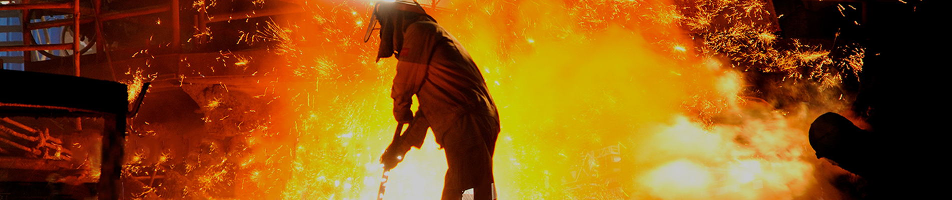
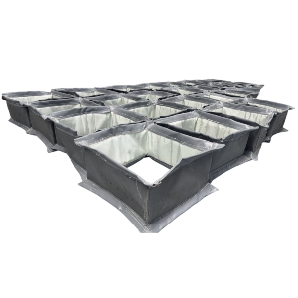
Adikdörtgen kumaş genleşme derziEndüstriyel havalandırma kanallarının büyük kare veya dikdörtgen bölümleri arasında esnek bir bağlantı sağlar. Bu sayede kanal sistemi, bitişik ekipman ve desteklere aşırı yük aktarmadan termal genleşmeyi, yanal yer değiştirmeyi, titreşimi ve yapısal hareketi karşılayabilir.
Dikdörtgen tasarımlar özellikle enerji üretim kanallarında, kazan sistemlerinde, çimento fabrikalarında, çelik fabrikalarında, fırınlarda, hava kirliliği kontrol ekipmanlarında ve gaz yolunun çok büyük olduğu veya geometrik olarak geleneksel yuvarlak bağlantıya uygun olmadığı diğer tesisatlarda yaygındır.
Basit bir esnek kumaş banttan farklı olarak, endüstriyel dikdörtgen genleşme derzinin dört düz kenarı, dört köşesi, basınç yönü, hareketi, proses sıcaklığı ve iç gaz akışı dikkate alınarak tasarlanması gerekir. Köşe yapısı ve uzun kenar stabilitesi, esnek malzemenin seçimi kadar önemli hale gelebilir.
BSTFLEX özel üretim yapmaktadır.Metal Olmayan Kumaş Genleşme DerzleriDikdörtgen, kare, yuvarlak ve özel endüstriyel havalandırma kanalları için.
Dikdörtgen Kumaş Genleşme Derzi — Temel Mühendislik Girişleri
Genişlik × Yükseklik | Yüz Yüze Uzunluk | Sıcaklık | Basınç | Proses Gazı | Eksenel Hareket | Yanal Hareket | Köşe Tasarımı | Gaz Hızı | Toz Yükü | Astar Konfigürasyonu
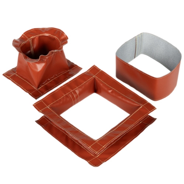
Büyük endüstriyel gaz taşıma sistemleri, genellikle dikdörtgen veya kare kanallar şeklinde üretilir çünkü bu geometri, büyük ekipman açıklıkları ve yapısal düzenlemelerle verimli bir şekilde entegre edilebilir.
Tipik örnekler arasında şu bağlantılar yer alır:
Bu kanallar ısındıkça ve soğudukça boyutları değişir. Bölümler arasındaki rijit bağlantı, termal genleşmeyi kanal duvarlarına, flanşlara, desteklere ve ekipmanlara aktarabilir.
Adikdörtgen kanal genleşme derziBu hareketin karşılanabileceği kontrollü ve esnek bir alan yaratır.
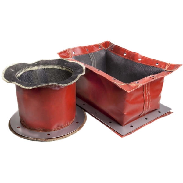
Temel çalışma prensibi benzerdir, ancak dikdörtgen geometri ek tasarım zorlukları ortaya çıkarır.
Dairesel bir bağlantı, geometrinin çevresine sürekli olarak dağılmasını sağlar. Dikdörtgen bir bağlantı ise şunları içerir:
Eklem sıkıştığında, genişlediğinde veya yana doğru hareket ettiğinde, bu bölgeler mutlaka aynı şekilde deforme olmaz.
Bu nedenle mühendisler, yalnızca düz bant bölümlerini değerlendirmek yerine, tüm çevreyi dikkate almalıdırlar.
Dikdörtgen biçimli kumaş genleşme derzlerinde köşeler en önemli detaylar arasındadır.
Esnek malzeme, bükülme veya çekme gerilimini yoğunlaştıran bir köşe geometrisine zorlanırsa, düz bölümler iyi durumda kalsa bile, tekrarlanan termal döngüler yerel aşınmaya neden olabilir.
İyi bir köşe tasarımı, gereksiz kumaş yoğunlaşmasını önlerken, bitişik kenarlar arasında hareketin sorunsuz bir şekilde geçişine olanak sağlamalıdır.
Bağlantı yapısına bağlı olarak, köşe geometrisi aşağıdaki yöntemler kullanılarak tasarlanabilir:
Uygun yöntem, boyutlara, kayış yapısına, hareket ve çalışma koşullarına bağlıdır.
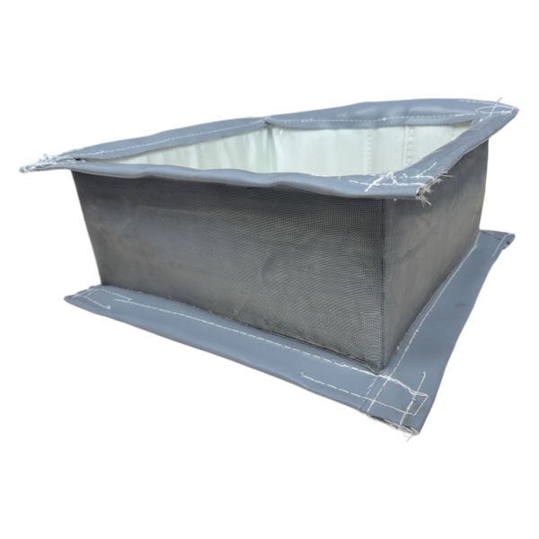
Dikdörtgen şeklindeki kanalların boyutları arttıkça, uzun kenarlar basınç ve yapısal hareketlerden kaynaklanan deformasyona daha yatkın hale gelir.
Pozitif basınç altında, geniş esnek alanlar dışa doğru hareket etme eğiliminde olabilir.
Negatif basınç altında, bunlar kanalın içine doğru çekilebilirler.
Boyutlar arttıkça etki daha belirgin hale gelir.
Bu nedenle, çok büyük bağlantılar için tasarımcıların şunları dikkate alması gerekebilir:
Dikdörtgen birleşim yerinin özelliklerini belirlerken üç boyut özellikle önemlidir.
| Boyut | Neyi Temsil Ediyor | Neden Önemli? |
|---|---|---|
| Genişlik | Yatay kanal boyutu | Bir çift düz kenarı tanımlar |
| Yükseklik | Dikey kanal boyutu | İkinci düz kenar çiftini tanımlar. |
| Yüz Yüze | Bağlantı düzlemleri arasındaki mesafe | Esnek açıklık ve hareket imkanı sağlayan etkiler mevcuttur. |
Yenileme projelerinde, bu ölçüler fotoğraflardan tahmin edilmek yerine, fiilen kurulu sistemden alınmalıdır.
Kumaş bir kemerin, belirtilen hareketi karşılayabilmesi için yeterli serbest geometriye sahip olması gerekir.
Yüz yüze mesafe çok kısa iken yanal hareket büyükse, esnek malzeme yüksek gerilime maruz kalabilir.
Öte yandan, aşırı miktarda gevşek kumaş eklemek, kontrolsüz katlanmalara ve iç bileşenlerle temasa neden olabilir.
Bu nedenle bağlantı, hem mevcut montaj alanına hem de gerekli yer değiştirmeye göre oranlanmalıdır.
Eksenel hareket, kanalın ana yönü boyunca gerçekleşir.
Şunları içerir:
Her iki değer de ayrı ayrı belirtilmelidir.
Örneğin:
Eksenel Sıkıştırma: 35 mm
Eksenel Uzatma: 10 mm
Bu, yalnızca "toplam 45 mm hareket" belirtmekten çok daha faydalı mühendislik bilgisi sağlar.
Büyük endüstriyel havalandırma kanalları sıklıkla kanal merkez hattına dik yönde hareketlere maruz kalır.
Bu durum şunlardan kaynaklanabilir:
Bunun başlıca avantajlarından biri şudur:kumaş kanal genleşme derziNispeten kısa bir montaj uzunluğu içinde önemli yanal yer değiştirmeyi absorbe edebilme yeteneğidir.
Ancak, yatay ve dikey yanal hareketler büyük dikdörtgen bir düzeneğe farklı talepler getirebileceğinden, gerekli hareket yönünün yine de net bir şekilde belirlenmesi gerekir.
Bağlantı yüzeylerinden birinin diğerine göre dönmesi durumunda açısal hareket meydana gelir.
Dikdörtgen birleşim yerinde, bu durum çevrenin farklı kısımlarının farklı miktarlarda hareket etmesine neden olur.
Bir taraf sıkışırken, karşı taraf genişleyebilir.
Açısal hareket bekleniyorsa, bu durum montaj toleransı olarak ele alınmak yerine orijinal tasarıma dahil edilmelidir.
Birçok endüstriyel havalandırma kanalı aynı anda eksenel, yanal ve açısal hareketlere maruz kalır.
Örneğin, sıcak bir fırın çıkışı eksenel olarak genişleyebilirken, yapısal genleşme aşağı yöndeki kanalı yana doğru kaydırabilir.
Dikdörtgen şeklinde bir kumaş genleşme derzi, bu tür birleşik yer değiştirmeyi karşılayabilir, ancak derz geometrisi toplam hareket aralığına göre tasarlanmalıdır.
Daha iyi teklif talebi verileri:
Eksenel Sıkıştırma: 30 mm
Eksenel Uzatma: 10 mm
Yatay Yanal: ±25 mm
Dikey Yanal: ±15 mm
Açısal Hareket: 1,5°
Kemer tipi tasarımda, mevcut veya imal edilmiş metal çerçevelerin çevresine takılan esnek bir kumaş eleman kullanılır.
Bu yapı yaygın olarak kullanılmaktadır çünkü esnek bant genellikle çevresindeki çelik yapıdan ayrı olarak bakımı yapılabilmektedir.
Olası avantajlar şunlardır:
Bakım projelerinde, mevcut metal aksamın uygun olması koşuluyla, bazen komple çelik aksamın değiştirilmesine gerek kalmadan yedek bir kayış üretilebilir.
Bazı projeler esnek kayıştan daha fazlasını gerektirir.
BSTFLEX aşağıdaki bileşenleri içeren komple sistemleri değerlendirebilir:
Yeni bir sistem üretilirken veya mevcut çelik yapı yıprandığında, komple bir montaj faydalı olabilir.
Özellikle yüksek hızlı veya partikül yüklü gaz taşıyan büyük dikdörtgen kanallarda iç astar çok önemli olabilir.
Astar, ana gaz akışı ile esnek kumaş elemanı arasında koruyucu bir bariyer oluşturur.
İşlevleri şunları içerebilir:
Astar, kanal bölümlerinin birbirlerine göre hareket etmesine yine de izin vermelidir.
Bir kaplama, genleşme derzlerinin hareketinden bağımsız olarak tasarlanamaz.
Yeterli boşluk bırakılmadığı takdirde, hareketli kanal bölümleri, astar bileşenlerinin birbirine müdahale etmesine neden olabilir.
Olası sonuçlar şunlardır:
Bu nedenle, astar örtüşmesi ve boşluğu, maksimum eksenel ve yanal yer değiştirmeye göre değerlendirilmelidir.
Çimento fabrikalarında, enerji santrallerinde ve diğer tozlu işlemlerde kullanılan dikdörtgen derzler, astarın arkasındaki boşlukta partikül madde biriktirebilir.
Biriken toz, zamanla hareket için gerekli alanı kaplayabilir.
Bu durum şunlara yol açabilir:
Bu nedenle, uygun uygulamalarda astar ile esnek bant arasına bir birikim bariyeri yerleştirilebilir.
Birçok büyük baca gazı kanalı atmosfer basıncının altında çalışır.
Negatif basınç, esnek kayışı içe doğru çekme eğilimindedir.
Büyük dikdörtgen bir bağlantı noktasında, bu durum uzun kenarlar boyunca önemli deformasyona neden olabilir.
Tasarımda şu hususlar dikkate alınmalıdır:
Sadece "vakum" kelimesini vermek yeterli değildir. Teklif talebine gerçek tasarım basıncı da eklenmelidir.
Pozitif iç basınç, esnek kayışı dışarı doğru iter.
Bu durum şu noktalardaki yüklenmeyi artırabilir:
Daha büyük kanal boyutları, basınca bağlı kuvvetleri artırabilir; bu nedenle, gerçek çalışma ve tasarım basıncı her zaman belirtilmelidir.
Dikdörtgen geometri tek başına malzemeyi belirlemez.
Esnek eleman, sıcaklık, gaz bileşimi, basınç ve çevresel gereksinimler dikkate alınarak seçilmelidir.
Olası malzeme sistemleri şunlardır:
| Malzeme | Olası İşlev |
|---|---|
| Fiberglas Kumaş | Takviye ve ısıya dayanıklı tekstil desteği |
| Silikon Kaplı Fiberglas | Esnek dış veya sızdırmazlık katmanı |
| PTFE Kaplı Kumaş | Kimyasal dirençli gaz bariyeri |
| Silika Kumaş | Yüksek sıcaklıkta yüz koruması |
| Isı Yalıtımı | Esnek montaj yoluyla sıcaklığın düşürülmesi |
| Metal Örgü veya Astar | Aşınma ve akış koruması |
Ayrıntılı malzeme karşılaştırması için kılavuzumuza bakın.Kumaş Genleşme Derz Malzemeleri: PTFE, Silikon, Fiberglas ve Silika.
Büyük kazanlar, fırınlar ve baca gazı kanalları, bazı esnek sızdırmazlık malzemelerinin pratik doğrudan maruz kalma sınırlarının ötesindeki sıcaklıklarda çalışabilir.
Genleşme derzinde her katmanın tam işlem sıcaklığına dayanması şartı yerine, çok katmanlı termal tasarım kullanılabilir.
Tipik bir fonksiyonel sıralama şunları içerebilir:
Sıcak Gaz
↓
Akış Astarı
↓
Yüzde Sıcaklık Koruması
↓
Yalıtım Katmanı
↓
Takviye
↓
Esnek Gaz Sızdırmazlık Elemanı
Gerçek yapı her zaman proses sıcaklığı, dengesizlik sıcaklığı, gaz hızı ve kimyasal koşullar dikkate alınarak belirlenmelidir.
Enerji üretim ekipmanları çok sayıda büyük dikdörtgen gaz yolu içerir.
Potansiyel lokasyonlar şunlardır:
Bu sistemler yüksek sıcaklık, termal hareket, titreşim, negatif basınç ve uçucu külü bir araya getirebilir.
Sonuç olarak, astar tasarımı ve partikül kontrolü, kumaş bant malzemesi kadar önemli olabilir.
Çimento işleme kanalları özellikle şiddetli aşınma ve birikme koşulları yaratır.
Başvurular şunları içerebilir:
İç koruma tasarımı yetersizse, çimento tozu genleşme derz boşluğuna girebilir ve hareketi engelleyebilir.
Bu uygulamalar için, parçacık koşullarını ve gaz hızını, sıcaklık ve hareket verileriyle birlikte sağlayın.
Çelik fabrikaları ve endüstriyel fırın tesislerinde dikdörtgen kanal bağlantıları yüksek gaz sıcaklığına ve yayılan ısıya maruz kalabilir.
Tipik tasarım öncelikleri şunlardır:
Ek ısı koruması gerektiğinde yüksek silika içerikli kumaşlar ve uygun yalıtım malzemeleri değerlendirilebilir.
Büyük endüstriyel fanlar genellikle dikdörtgen şekilli havalandırma kanallarına doğrudan bağlanır.
Bu bölgelerde, genleşme derzinin öncelikle şu işlevleri yerine getirmesi gerekebilir:
Bu nedenle malzeme yapısı, doğrudan yüksek sıcaklıktaki fırın çıkışında bulunan bir bağlantıdan çok farklı olabilir.
| Tasarım Faktörü | Dikdörtgen Kumaş Bağlantısı | Dikdörtgen Metal Körük |
|---|---|---|
| Birincil Esnek Eleman | Teknik kumaş veya kompozit kemer | Şekillendirilmiş metal |
| Tipik Hizmet | Büyük düşük basınçlı gaz kanalları | Mühendislik ürünü metalik kanal sistemleri |
| Büyük Boyutlar | Son derece pratik | Mümkün ancak mekanik olarak daha karmaşık |
| Yanal Hareket | Yüksek esneklik | Körük konfigürasyonuna bağlıdır. |
| Yay Kuvvetleri | Genellikle düşük | Daha yüksek ve tasarıma bağlı |
| Malzeme Sistemi | Termal ve kimyasal katmanları birleştirebilir. | Metal alaşımı bazlı |
| Esnek Eleman Değişimi | Kayış ayrı olarak değiştirilebilir. | Körük tertibatı genellikle değiştirilir veya onarılır. |
Evrensel olarak kabul görmüş tek bir maksimum boyut yoktur.
Kumaş genleşme derzleri, özellikle büyük kanal boyutları için uygundur çünkü esnek eleman, büyük şekillendirilmiş dairesel bir körük gerektirmek yerine, gerekli çevre boyunca imal edilebilir.
Pratik boyut sınırları şunlara bağlıdır:
Şantiye koşulları gerektirdiğinde, çok büyük yapılar taşınabilir bölümler halinde tasarlanabilir.
Büyük dikdörtgen şeklindeki parçaların tek parça halinde taşınması zor olabilir.
Boyutlara ve proje gereksinimlerine bağlı olarak, metal çerçeve şu özelliklere sahip olabilir:
Montaj öncesinde çerçeve deformasyonunu önlemek için geçici nakliye kısıtlamalarına da ihtiyaç duyulabilir.
Taşıma yöntemi, üretim tamamlandıktan sonra değil, tasarım aşamasında dikkate alınmalıdır.
Yenileme projeleri, yalnızca genişlik ve yükseklik bilgisinden daha fazlasını gerektirir.
Yedek parça üretmeden önce şunları toplayın:
Mevcut bağlantı erken arızalandıysa, hasarlı bölgelerin fotoğraflarını çekin ve gözlemlenen arızayı açıklayın.
Eski endüstriyel havalandırma kanalları her zaman mükemmel kare şeklinde değildir.
Uzun süreli termal döngüler, üretim toleransı ve yapısal hareketler, karşıt taraflar arasında boyut farklılıkları yaratabilir.
Yenileme projeleri için ölçüler:
Bu, tek bir nominal genişlik × yükseklik ölçümünden görülemeyecek bozulmaları ortaya çıkarabilir.
Bir kumaş birleşimi, belirtilen hizalama hatalarını telafi edebilir, ancak sınırsız üretim hatasını otomatik olarak absorbe etmesi beklenmemelidir.
Büyük kalıcı sapma, normal termal çalışma için mevcut hareket kabiliyetini azaltır.
Bu nedenle, bilinen herhangi bir soğuk pozisyon hizalama hatası, yedek bağlantı parçası üretilmeden önce bildirilmelidir.
Denetim sırasında özellikle şu hususlara dikkat edilmelidir:
Tipik arıza belirtileri şunlardır:
Doğru bir mühendislik değerlendirmesi için, teklif talebi (RFQ) aşağıdaki bilgileri içermelidir:
| Kanal Genişliği | Gerçek genişlik (mm veya inç cinsinden) |
| Kanal Yüksekliği | Gerçek yükseklik (mm veya inç cinsinden) |
| Yüz Yüze Uzunluk | Bağlantı düzlemleri arasındaki monte edilmiş mesafe |
| Çalışma Sıcaklığı | Sürekli işlem sıcaklığı |
| Maksimum Sıcaklık | En yüksek değer ve maruz kalma süresi |
| Basınç | Pozitif veya negatif işletme ve tasarım basıncı |
| İşlem Ortamı | Sıcak hava, egzoz, baca gazı veya diğer proses gazı |
| Eksenel Sıkıştırma | Eklem yönüne doğru gerekli hareket |
| Eksenel Uzatma | Eklemden uzaklaşmak için gerekli hareket |
| Yatay Yanal | Yanal hareket gerekli |
| Dikey Yanal | Gerekli dikey hareket |
| Açısal Hareket | Gerekiyorsa rotasyon zorunludur. |
| Gaz Hızı | Kanal boyunca akış hızı |
| Parçacıklar | Toz, uçucu kül veya aşındırıcı katı maddeler |
| Astar | Mevcut veya gerekli iç astar detayları |
| EK | Kayış, cıvatalı flanş veya kaynaklı montaj |
Özel dikdörtgen bir bağlantı için, faydalı bir çizimde şunlar gösterilmelidir:
Karmaşık montajlar için CAD çizimleri tercih edilir, ancak net bir boyutlandırılmış PDF veya mühendislik çizimi de ilk değerlendirme için yeterli bilgi sağlayabilir.
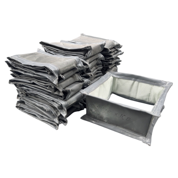
BSTFLEX özel üretim yapmaktadır.dikdörtgen kumaş genleşme derzleriSıcak hava, egzoz gazı, baca gazı ve diğer proses gazlarını taşıyan endüstriyel havalandırma sistemleri için.
Tasarımlar, müşteriye özel kanal boyutları, çalışma sıcaklığı, pozitif veya negatif basınç, hareket, gaz kimyası, hız ve partikül koşulları dikkate alınarak geliştirilebilir.
Mevcut yapılar, uygulama gereksinimlerine göre fiberglas, silikon kaplı kumaş, PTFE bazlı malzemeler, silika kumaş, yalıtım katmanları ve iç koruyucu sistemleri bir araya getirebilir.
Ürünle ilgili tüm bilgilere ulaşmak için lütfen web sitemizi ziyaret edin.BSTFLEX Metal İçermeyen Kumaş Genleşme Derzisayfa.
Genişlik × yükseklik, yüz yüze uzunluk, normal ve maksimum sıcaklık, basınç, proses gazı, eksenel hareket, yatay ve dikey yanal hareket, gaz hızı, partikül koşulları ve mevcut çizimleri gönderin.
öncesi :
Yüksek Silika Kumaş Nedir?sonraki :
Metal Olmayan Genleşme Derzi Nedir?
 English
 français
 Deutsch
 русский
 italiano
 español
 português
 Nederlands
 العربية
 日本語
日本語 한국의
한국의 Polski
 Tiếng Việt
 slovenský
 Indonesia